SCR-CCR-01
IPRS Băneasa
- Also known as
- SCR-F-01, P 345-SCR-AI-01
- Manufacturer
- IPRS Băneasa

- Country
- Romania

- Year
- Unknown
- Category
- Industrial Electronics
- Type
- Industrial equipment
- Documentation score
- 1/5
- Last edited
- 25 OCT 2026
Specifications
- Application
- control and regulation of single-phase and three-phase thyristor converters
- Dimensions
- 19 different values (see Variants)
Sources: [1]
Variants (28)
| Note | Compare | ||
|---|---|---|---|
| P1-SCR-SSF-01 | 188.5 × 132.5 × 45 mm | phase-sequence signalling module | |
| P2-SCR-SA-01 | 192 × 132.5 × 105 mm | supply voltage module | |
| P 345-AI-01 | 188.5 × 132.5 × 40 mm | pulse amplifier module (printed „P 345-SCR-AI-01” and „P345-SCR-AI-01” on pp. 10-27…10-28) | |
| P6-SCR-DCG-01 | 188.5 × 132.5 × 30 mm | gate-control module | |
| P7-SCR-R-01 | 188.5 × 132.5 × 30 mm | regulation module | |
| P7-SCR-RA-01 | 188.5 × 132.5 × 30 mm | adaptive regulator module | |
| P8-SCR-EL-01 | 188.5 × 132.5 × 30 mm | current balancing module | |
| P9-SCR-PR-01 | 188.5 × 132.5 × 55 mm | relay board module | |
| P10-SCR-2TC-01 | 188.5 × 132.5 × 45 mm | current transducer module | |
| P11-SCR-2TT-01 | 188.5 × 132.5 × 50 mm | voltage transducer module | |
| SCR-SA-02 | 190 × 132.5 × 30 mm | power supply module | |
| SCR-DCG-02 | 190 × 132.5 × 30 mm | gate-control module | |
| SCR-R-02 | 190 × 132.5 × 35 mm | regulation module (SCR-F-01 system) | |
| SCR-TEST-01 | 200 × 132.5 × 50 mm | checking module (SCR-F-01 system) | |
| SCR-TEST-02 | 200 × 132.5 × 50 mm | checking module (SCR-F-01 system) | |
| SCR-ASE-01 | 190 × 132.5 × 30 mm | signal conversion and balancing module | |
| SCR-PLC-01 | 190 × 132.5 × 35 mm | current limiting and protection module | |
| SCR-DCG-03 | 190 × 132.5 × 40 mm | gate-control module (single-phase converter) | |
| SCR-R-03 | 190 × 132.5 × 40 mm | regulation module (SCR-F-01 system) | |
| SCR-TEST-03 | 200 × 132.5 × 70 mm | checking module (SCR-F-01 system) | |
| SCR-TI-01 | 59.5 × 50 × 50 mm | pulse transformer | |
| SCR-TAI-01 | 126 × 99 × 96.5 (printed without a unit) | power transformer | |
| SCR-SM-03 | 285 × 221 × 132.5 mm | 4-module frame | |
| SCR-SM-04 | 221 × 186 × 132.5 mm | 3-module frame | |
| SCR-SM-05 | 395 × 221 × 132.5 mm | 6-module frame | |
| SCR-SM-06 | 495 × 219 × 132.5 mm | 8-module frame | |
| SCR-SM-07 | 269 × 260 × 196 mm | 7-module frame | |
| SCR-SM-08 | 260 × 235 × 134.5 mm | 3-module frame |
Click a column heading to sort. „+” adds a variant to the comparison (SCR-CCR-01).
Description
The SCR-CCR-01 is a control and regulation system (control assembly) for single-phase or three-phase thyristor converters at mains frequency, made by IPRS Băneasa [1].
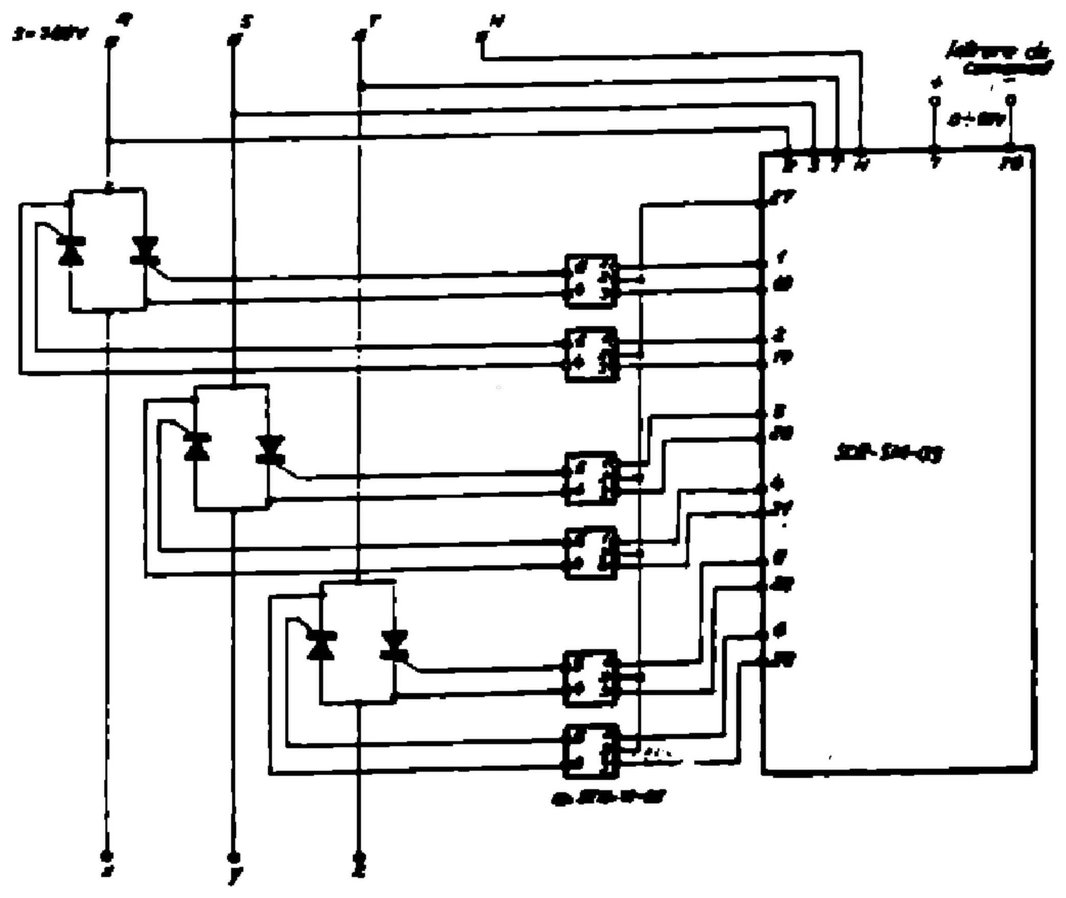
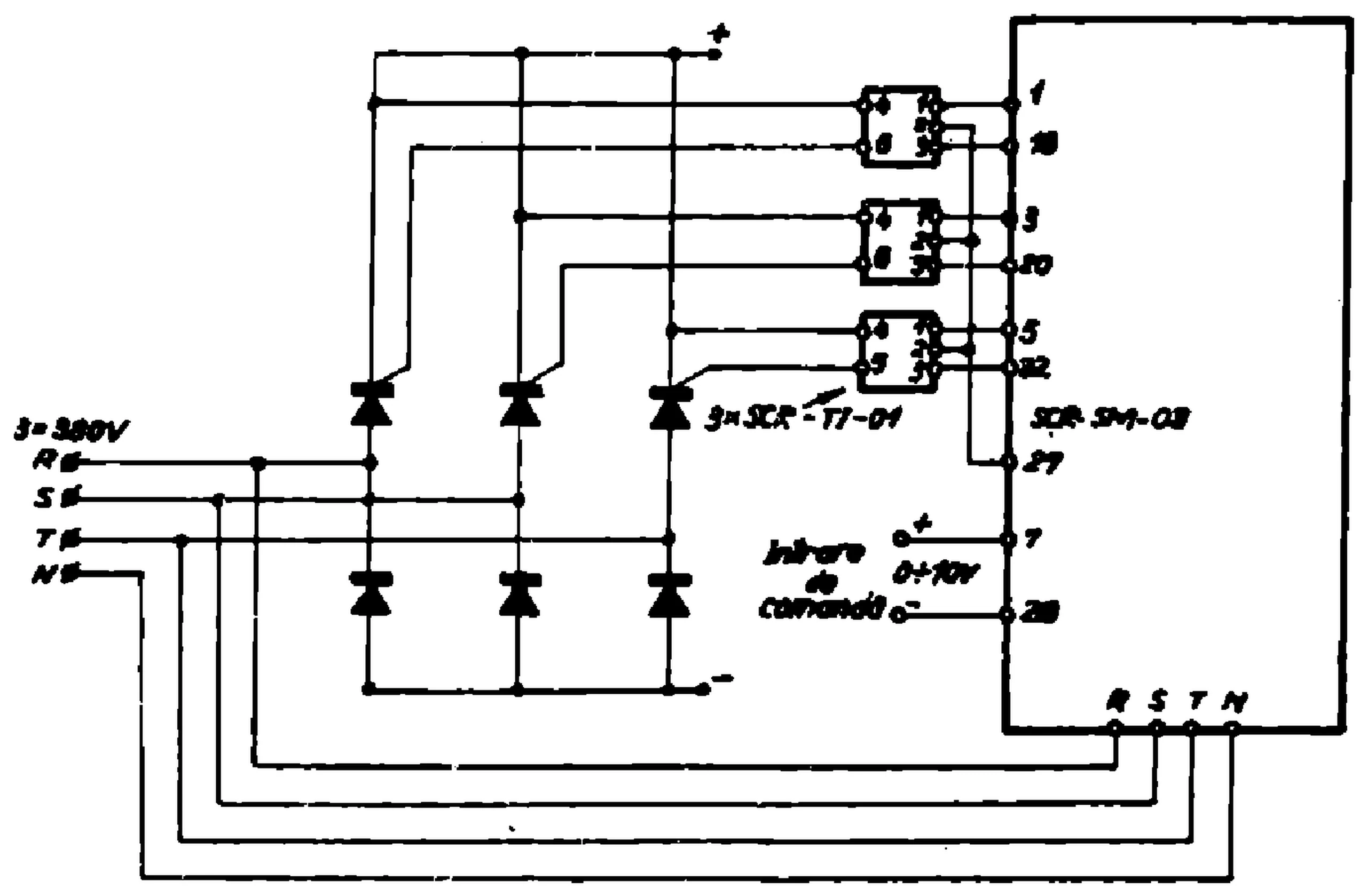
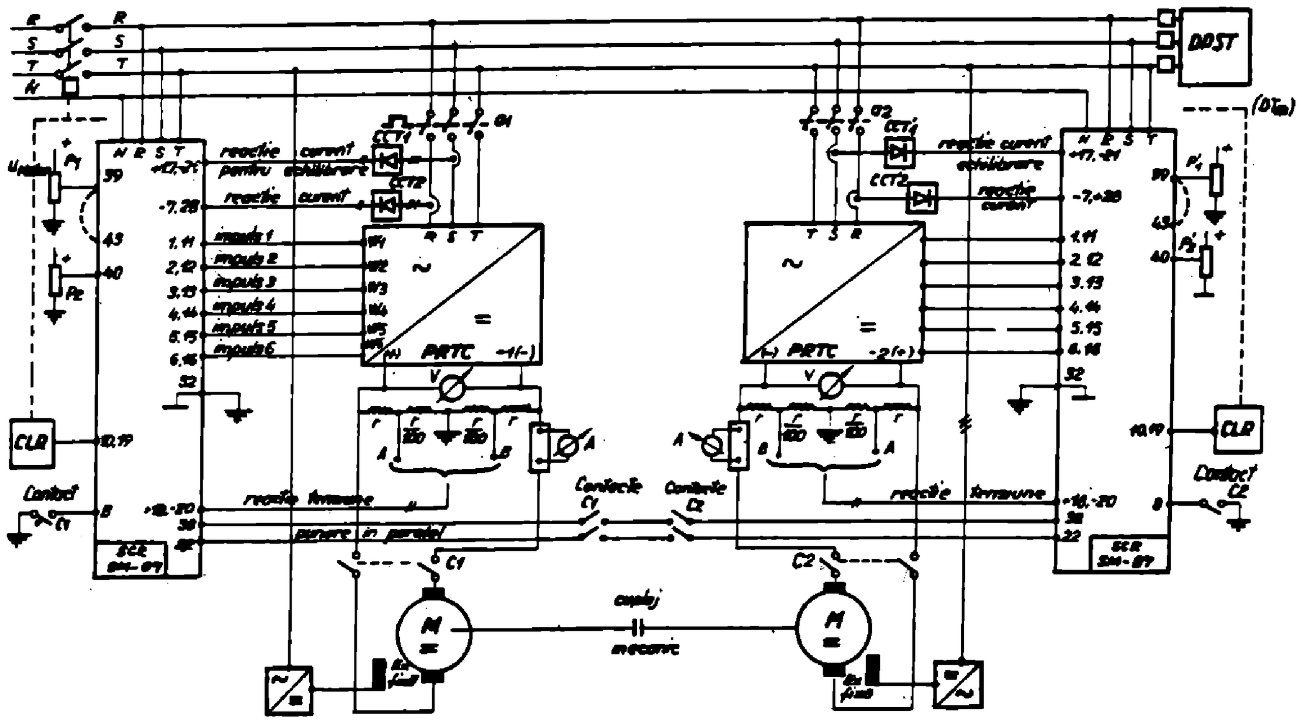
The I.P.R.S. Băneasa Full Line Condensed Catalog (1990) explains that, thanks to the modular design, the configuration can easily be modified by the user; the modules are built on EUROCARD type PCBs (100 × 160 mm), with an operating temperature range of −25…+40 °C and a storage temperature range of −40…+55 °C [1]. The modules available in 1990, the transformers and the modular frames are listed under Variants (with their dimensions); other frame types were available on request [1]. Three application schematics are in the Gallery: a three-phase A.C. converter and a three-phase converter (p. 10-29), and a power controller with two D.C. motors (p. 10-30) [1].
The phase-sequence signalling module (P1-SCR-SSF-01) checks whether the supply voltages of the control and regulation unit are in normal or reverse sequence and whether a phase is missing: with supply voltages of ±15 V (±5 %) / 20 mA and +24 V (±30 %) / 30 mA, its relay contact is closed for the normal sequence of phases and open for the reverse sequence or a missing phase [1]. The supply voltage module (P2-SCR-SA-01) supplies the whole system with regulated and unregulated voltages and with synchro voltages: from 3 × 380 Vac (+10 % / −15 %) it gives +15 V (±5 %) / 400 mA, −15 V (±5 %) / 400 mA, +24 V (±30 %) / 600 mA and 3 × 60 Vac (synchro voltages), the regulated voltages being short-circuit protected [1].
The pulse amplifier module (P 345-AI-01) amplifies the trigger pulses generated by the gate-control module when parallel-connected thyristors are used (SCR-TI-01 pulse transformers are required); it takes +24 V (±30 %) / 100 mA, 22 Vac / 50 Hz / 1.5 A and 43 Vac / 50 Hz / 1 A (the AC voltages with 6 SCR-TI-01), a control voltage of +24 V / 25 mA, and gives a pulse voltage of 24 Vcc / 1 ms (48 V / 100 µs peak), with a maximum load of 6 SCR-TI-01 transformers [1].
The gate-control module (P6-SCR-DCG-01) delivers 6 double-pulses for the control of thyristor converters such as fully-controlled three-phase bridges, commanded rectifiers with absorbtion choke and static three-phase contactors; the pulse width is 1 ms and can be enlarged on request up to 10 ms for strong inductive loads [1]. It takes ±15 V (±5 %), +24 V (±30 %) and 3 × 60 Vac (±20 %) at 50 Hz (±2 %; for other frequency values in the range going from 54 to 60 Hz, extra-adjustments are needed, as printed), a control voltage of 0…+10 V / < 100 µA, with a control range of 170 electric degrees; the pulse location is adjustable from 5 to at least 60 electric degrees (rectifier range) and from 100 to 175 electric degrees (inverter range), the regulation domain of the pulses being shifted 30 electric degrees with respect to the respective phase [1]. It gives 6 pulses per full cycle (the auxiliary pulse shifted 60 electric degrees from the main pulse), with an interval of 60 ± 3 electric degrees, a pulse width of 1 ms (±50 % for a control voltage of +5 volts) and a pulse voltage of 24 V (±30 %) / 0.6 A for one SCR-TI-01 transformer; the pulses are blocked through grounding [1].
The regulation module (P7-SCR-R-01) is designed for the voltage control of thyristor converters with a current monitoring loop; thanks to its circuitry, no thyristor trigger pulses appear at power switch-on; it has supply voltages of ±15 V (±5 %) and +24 V (±30 %), an input signal below 1 mA at the voltage regulator and below 0.2 mA at the current regulator, a typical output voltage of 0…+5 V (2 kohm load), a start delay below 300 ms and an integration time below 6 s (both adjustable) [1]. The adaptive regulator module (P7-SCR-RA-01) controls the output voltages of thyristor converters with a current monitoring loop, with supply voltages of ±15 V (±5 %) and +24 V (±30 %), an input signal below 1 mA at the voltage regulator and below 0.1 mA at the current regulator, a typical output voltage of 0…+5 V (2 kohm load), a start delay below 600 ms and an integration time below 2 s (both adjustable) [1]. The current balancing module (P8-SCR-EL-01) is intended for current balancing and power limiting for thyristor converters driving two D.C. motors coupled on the same axis: supply voltages ±15 V (±5 %) / 25 mA, input signal 0…10 V, output signals 0…+10 V and −10…+10 V, comparation error below ±5 % [1].
The relay board module (P9-SCR-PR-01) controls various electrical circuits requiring galvanic insulation; it has 5 relays, 4 of them commanded by a logic signal (0…+5 V or 0…+15 V) and one by a programmable voltage level from −12 to +12 V; supply voltages ±15 V (±5 %), control voltage +5 V or +15 V, or grounding / a programmable signal from −12 V to +12 V, control current 0.25 mA (+5 V), 0.75 mA (+15 V) and 0.25 mA (programmable level signal), relay contact voltage at most 220 Vac and relay contact power at most 50 W [1]. The current transducer module (P10-SCR-2TC-01) gives current information (single polarity only) through a transducer with galvanic insulation, which requires a current shunt; there are two current transducers on a module, with supply voltages of ±15 V (±5 %) / 20 mA and +24 V (±30 %) / 10 mA, a 75 mV type shunt, a transfer ratio of 0.02 V/mV, a transfer ratio error of ±4 % (20…100 mV) and ±10 % (10…20 mV and 100…150 mV), a linear range of at most 20…100 mV and a voltage to be compared of 0.75…15 V [1]. The voltage transducer module (P11-SCR-2TT-01), a double polarity voltage transducer with galvanic insulation, has two transducers on a module, a supply voltage of +24 V (±30 %) / 40 mA, an input voltage of 0…±10 V, a transfer ratio of 0.85 V/V, a transfer ratio error of at most ±10 %, a linearity error of at most ±5 %, a zero error of at most ±20 % and a maximum linearity range of 150 % [1].
The power supply module (SCR-SA-02) supplies the whole system with regulated and unregulated voltages: from 2 × (3 × 9.5 Vac) and 3 × 11 Vac (+10 % / −15 %), at a mains frequency of 50 Hz (±2 %), it gives +15 V (±2 %) / 400 mA, −15 V (±2 %) / 400 mA and +24 V (±30 %) / 600 mA [1]. The gate-control module (SCR-DCG-02) also delivers 6 double-pulses for fully-controlled three-phase bridges, commanded rectifiers with absorbtion choke and static three-phase contactors, with the same supply voltages, control voltage, control range, pulse locations, pulses and pulse interval as the P6-SCR-DCG-01, a pulse width of 1 ms (±15 % for a +5 V control voltage) and a pulse voltage of 24 V (±30 %) / 1.2 A for two SCR-TI-01 transformers connected in parallel [1].
Several modules are described as parts of the SCR-F-01 control and regulation system [1]. The regulation module (SCR-R-02) is designed for the voltage control of thyristor converters with a current monitoring loop: supply voltages ±15 V (±2 %) and +24 V (±30 %), input signal below 1 mA at the voltage regulator and below 0.1 mA at the current regulator, typical output voltage 0…+5 V (2 kohm load), start delay typically 900 ms and integration time typically 1 s (both adjustable) [1]. The regulation module (SCR-R-03) is designed for the voltage control of thyristor converters and commands a single current loop: the same supply voltages, an input signal below 0.1 mA at the current regulator, a typical output voltage of 0…+5 V (2 kohm load) and a typical start delay of 900 ms [1]. The checking modules contain an analog measuring device (SCR-TEST-01) or an electronic voltmeter with an analog measuring device (SCR-TEST-02, SCR-TEST-03) indicating the input voltage level of 12 signals selected through a front panel switch: the SCR-TEST-01 checks the voltage supplies and the gate control device (supply +24 V (±30 %) / 20 mA; inputs D.C. 0…±15 V, A.C. at most 60 Veff / 50 Hz, pulses of at most 24 V, 1 ms, 50 Hz; at most 1 mA per input), the SCR-TEST-02 some of the electronic circuits (supply ±15 V (±2 %) / 25 mA; inputs 0…±12 V, typically 3 µA per input), and the SCR-TEST-03 the voltage supplies, the gate control pulses and the electronic circuits (supply ±15 V (±2 %) and +24 V (±30 %); inputs 0…±12 V, at most 60 Veff / 50 Hz; at most 1 mA per input) [1].
The signal conversion and balancing module (SCR-ASE-01) translates electrical signals in the 0…10 V range and ensures a temporized current limiting in case of overload: supply voltages ±15 V (±5 %), input voltages 0…−10 V, 0…+10 V and −5…0…+5 V (differential) [1]. The current limiting and protection module (SCR-PLC-01) provides adjustable voltage steps for rotor current limiting, rotor overcurrent protection with instant pulse shift at 180 electric degrees, and comparison between the real voltage value, two prescribed voltages and the assigned voltage value: supply voltages ±15 V (±2 %) and +24 V (±30 %), input voltages −15…0…+15 V, current limiting thresholds of +8.4 V for 1.25 IN, +6.6 V for 1.0 IN, +5.1 V for 0.75 IN and +3.4 V for 0.5 IN, and a rotor overcurrent threshold of +13.3 V for 2.0 IN [1].
The gate-control module (SCR-DCG-03) delivers the drive pulses for the thyristors of a single-phase converter and the D.C. voltages needed by the system modules: supply voltages 2 × 18 Veff / 50 Hz, 22 Veff and 60 Veff (synchro voltage); output voltages ±15 V (±2 %) / 200 mA and +24 V (±30 %) / 600 mA; control voltage 0…+10 V / < 100 µA, with a control range of 175 electric degrees; pulse location adjustable from 18 to 75 electric degrees (rectifier range) and from 115 to 193 electric degrees (inverter range); 2 pulses per full cycle, with an interval of 180 ± 3 electric degrees, a pulse width of 1 ms (adjustable) and a pulse voltage of 24 V / 1.2 A for two SCR-TI-01 transformers [1].
The SCR-TI-01 pulse transformer transmits the gate drive pulses to the converter thyristors and provides, at the same time, galvanic insulation between the regulation and control system and the thyristor converter: primary pulse voltage +24 V, pulse frequency 50 Hz, pulse width 1 ms, secondary pulse voltage (no load) 10 volts, secondary pulse rise slope 1 A / 4 µs, short-circuit current 1.2 A [1]. The SCR-TAI-01 is a single-phase power transformer for the P 345-SCR-AI-01 pulse amplifier: primary 220 V / 110 VA, secondary 1 22.5 V / 100 VA, secondary 2 43 V / 10 VA [1].
The modular frames provide the connections between the modules, for the output slots and the transformers [1]. The SCR-SM-03 holds the P2-SCR-SA-01, P6-SCR-DCG-01, P7-SCR-R(RA)-01 and P10-SCR-2TC-01; the SCR-SM-04 is a frame for the P345-SCR-AI-01; the SCR-SM-05 holds the P2-SCR-SA-01, P6-SCR-DCG-01, P7-SCR-R(RA)-01, P9-SCR-PR-01, P10-SCR-2TC-01 and P11-SCR-2TT-01; the SCR-SM-06 holds the P1-SCR-SSF-01, P2-SCR-SA-01, P6-SCR-DCG-01, P7-SCR-R(RA)-01, P8-SCR-EL-01, P9-SCR-PR-01, P10-SCR-2TC-01 and P11-SCR-2TT-01; the SCR-SM-07 holds the SCR-SA-02, SCR-DCG-02, SCR-R-02, SCR-TEST-01, SCR-TEST-02, SCR-ASE-01 and SCR-PLC-01; and the SCR-SM-08 holds the SCR-DCG-03, SCR-R-03 and SCR-TEST-03 (one piece of each) [1].
Gallery
 No image available
 No image available
 No image available
Schematics
No schematics available yet.
Documents
No documents available yet.
References
- [1]I.P.R.S. Băneasa – „Full Line Condensed Catalog”, 1990, section 10 „Systems, equipments & tools”, „SCR-CCR-01 – Control and regulation system”, pp. 10-19…10-30