 No image available
S.E.C.U.
IPRS Băneasa
- Also known as
- Sistem Electronic de Control cu Ultrasunete, SC-DEF, SC-DIM
- Manufacturer
- IPRS Băneasa

- Country
- Romania

- Year
- Unknown
- Category
- Test & Measurement
- Type
- Ultrasonic testers
- Documentation score
- 2/5
- Last edited
- 25 OCT 2026
Specifications
- Function
- nondestructive ultrasonic control of laminated profiles: defectoscopy (SC-DEF) and wall thickness and diameter control (SC-DIM)
- Frequency range
- 0.5…6 MHz or 6…12 MHz, 500 kHz…20 MHz, 4…10 MHz (see Variants)
- Construction
- modular; modules mounted in a metallic frame
Sources: [1]
Variants (8)
| Note | Compare | ||
|---|---|---|---|
| M-ER | 0.5…6 MHz or 6…12 MHz | pulser–receiver module (SC-DEF) | |
| M-M | — | monitor module (SC-DEF) | |
| M-CG | 500 kHz…20 MHz | thickness control module (SC-DIM) | |
| M-CD | 4…10 MHz | diameter control module (SC-DIM) | |
| M-S | — | synchro module (SC-DIM) | |
| M-ED | — | defect-evaluation module (SC-DIM) | |
| M-CS | — | signal converter module (SC-DIM) | |
| M-AD | — | storage / comparator module (SC-DIM) |
Click a column heading to sort. „+” adds a variant to the comparison (S.E.C.U.).
Description
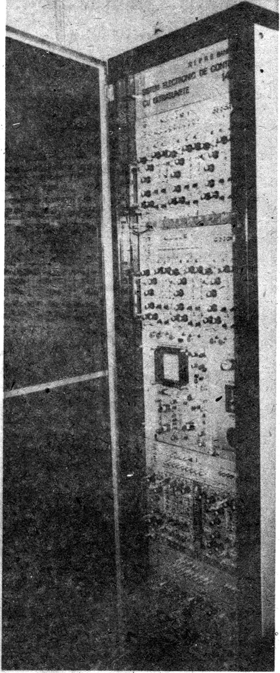
The S.E.C.U. (Sistem Electronic de Control cu Ultrasunete) is an ultrasonic electronic control system made by IPRS Băneasa, designed as part of the nondestructive ultrasonic control equipment for laminated profiles (bars, tubes, files etc.) made by the metal-working industry [1].
The I.P.R.S. Băneasa Full Line Condensed Catalog (1990) names its main parts: the defectoscopy-control system (SC-DEF) and the dimensional control system (SC-DIM); thanks to the modular design, the configuration can easily be modified by the user, and the modules can be ordered separately [1].
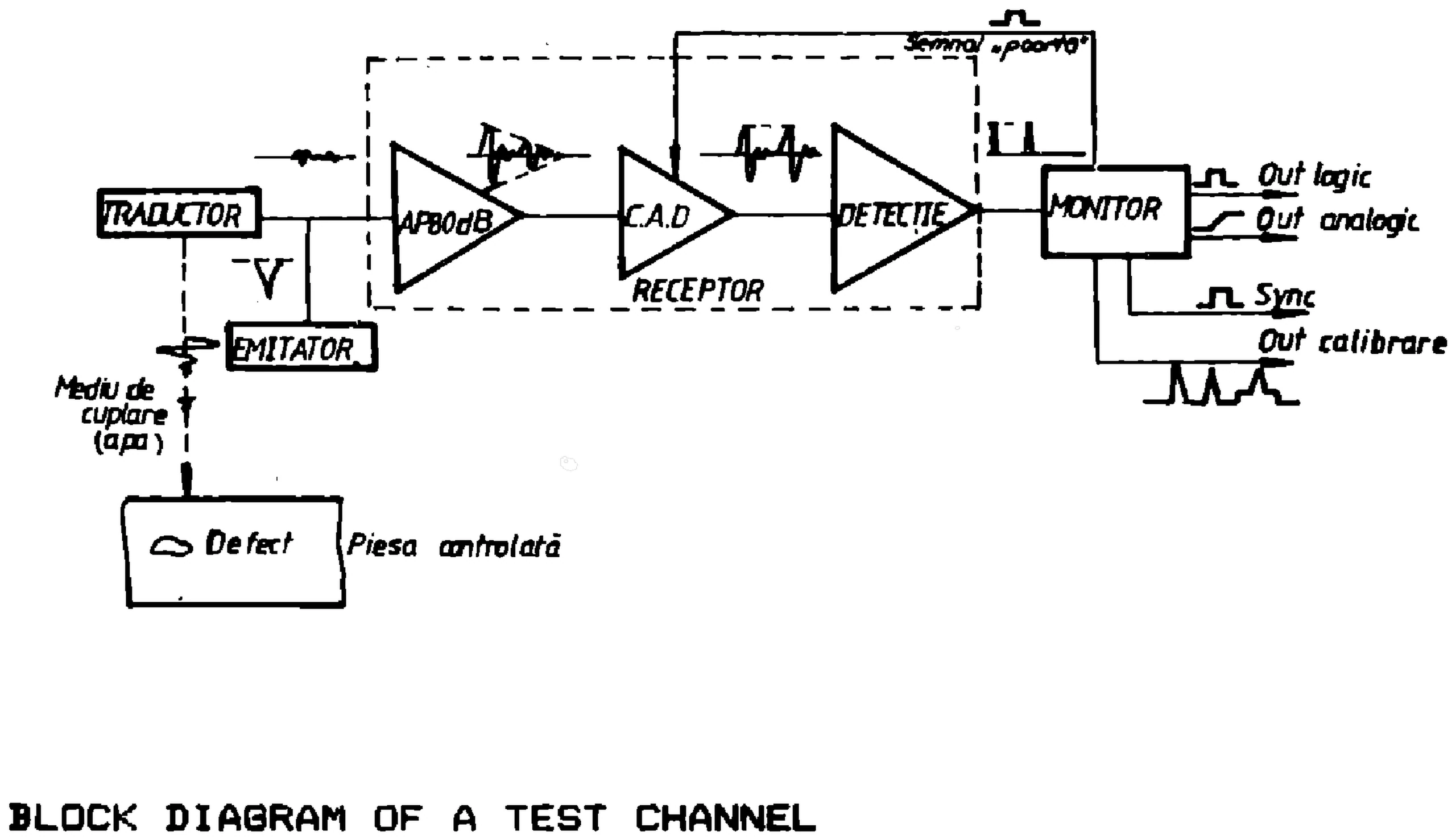
The SC-DEF is made of test channel combinations, its configuration being determined by the user’s control technology; the block diagram of a test channel, labelled in Romanian, is in the Gallery: a transducer („traductor”) coupled through water to the controlled piece, an emitter, a receiver (an 80 dB amplifier, „C.A.D” and detection stage) and a monitor with logic, analog, sync and calibration outputs [1]. The pulser–receiver module (M-ER) has a pulser with supply voltages of ±6.0 V, ±12 V and 117 V / 50 Hz, internal and external triggering (TTL levels) and a pulse width of 4.0 µs; with external triggering, a pulser can drive 8 identical units, and the transducer drive pulse is adjustable from the front panel: repetition frequency 500 Hz…10 kHz, rise time 30…80 ns, width 50…500 ns, amplitude 100…300 V [1]. Its receiver has supply voltages of ±6.0 V and ±12 V, a sensitivity of at least 1.6 mV, an amplification of at least 80 dB, adjustable coarse (0…70 dB in 10 dB steps) and fine (0…10 dB in 1.0 dB steps), a frequency range of 0.5…6 MHz or 6…12 MHz, a noise rejection of up to 50 % of the maximum output signal, and signal filtering switchable in two steps, which can also be cancelled [1].
The monitor module (M-M) works with direct and echo pulse triggering; the gate triggering pulse width is adjustable coarse (55 µs…4 ms) and fine (5…65 µs), the gate pulse width coarse (20 µs…2.2 ms) and fine (0.8…25 µs); it has two adjustable defect signalling levels, in steps, in the 0…100 % range, optical signalling by LED, an analog output (defect signalling) of 0…5 V, a logic output (defect signalling) of at most 10 mA with signal insulation through an opto-coupler, and a recorder output of 0…8 V [1]. The M-ER and M-M modules, with a power supply, are mounted in a metallic frame that ensures the mechanical fixture and the module interconnections for the required test channel configuration [1].
The SC-DIM measures the wall thickness and the diameter of various profiles and signals the deviations from the nominal values, which permits considerable material saving; its modules are compatible with the SC-DEF modules and frame, and the whole system contains 6 modules, for thickness control, diameter control, synchronisation, defect evaluation, signal conversion and storage / comparison [1]. A computer can be added (optionally) for further signal processing, value storage and a profile measurement data base [1].
The thickness control module (M-CG) uses the immersion or rotating method; its pulser gives a drive pulse amplitude (no load) of at least 250 V, a pulse width of 50…200 ns and a pulse rise time of 10…80 ns (both adjustable), an output impedance of at least 15 ohms, a trigger pulse amplitude of 5…15 V and a TTL-level SYNCHRO output pulse [1]. Its receiver has a gain of at least 60 dB (adjustable), a frequency range of 500 kHz…20 MHz, an input impedance of 15…250 ohms (adjustable), an adjustment range matching propagation speeds of 1…7 km/s through the object, and controlled thickness ranges of 1…19 mm (±10 µm), 4…40 mm (±0.1 mm) and 10…150 mm (±0.5 mm); the interface has logic outputs for wall thicknesses above the max. and below the min. values, a 3¾-digit display and a 50-ohm output impedance [1].
The diameter control module (M-CD) uses a 3-transducer method; its pulser gives a drive pulse amplitude (no load) of at least 250 V, a pulse rise time of 30 ns, an output impedance of 47…500 ohms and a pulse frequency of 1…5 kHz (both adjustable), with external synchro and negative-going-edge triggering at 5…15 V [1]. Its receiver has a frequency range of 4…10 MHz and an input impedance of 47…500 ohms (adjustable); the output voltage depends on the deviation from the set-point, with sensitivities of 20, 10 and 4 mV/µm for measuring ranges of ±0.4, ±1 and ±2 mm, null adjustments of ±0.25, ±0.5 and ±1 mm and distance measuring sensitivities of 2, 1 and 0.5 mV/µm; the accuracy is ±3 µm, the maximum eccentricity range 2 / 4 / 8 mm, and it has a digital display (in µm), an interference rejection stage and an operating temperature of 0…45 °C [1].
The synchro module (M-S) supplies the synchro pulses for all the SC-DEF and SC-DIM modules, with external triggering (the SC-DEF / SC-DIM modules synchronised by the rotating head, with the rotating method) or internal triggering (the SC-DEF synchro pulses generate trigger pulses for the SC-DIM modules); in both modes the synchro frequency of all the other modules is limited to a preset value of 1 or 5 kHz, and the operating temperature range is 0…45 °C [1]. The defect-evaluation module (M-ED) contains several comparators for the measured signal, with 4 independent channels (with signal summing facility) that can drive different storage / computing units: each channel has min./max. thresholds, a continuous tolerance adjustment, self-contained for min./max. values in the 0…100 % range, and indicators for exceeding them; it has open collector outputs and works at 0…45 °C [1].
The signal converter module (M-CS) is the interface between the M-CG / M-CD modules and a computer and/or graphic recorder; it has 4 identical channels, each with 2 sample / hold circuits for the minimum and maximum signal values, an input voltage swing of ±8 V, a minimum input pulse width of 20 µs, an input impedance of 100 kohms, a chopper frequency of 100 Hz, unity voltage gain, a 1 kohm output impedance and an operating temperature range of 0…45 °C [1]. The storage / comparator module (M-AD) counts the total number of defects and compares the value obtained with a preset one; it has 6 circuits on 3 boards, with summing signal facility, and all its inputs and outputs are buffered with opto-couplers [1].
Gallery
 No image available
Schematics
No schematics available yet.
Documents
No documents available yet.
References
- [1]I.P.R.S. Băneasa – „Full Line Condensed Catalog”, 1990, section 10 „Systems, equipments & tools”, „S.E.C.U. – Ultrasonic electronic control system”, pp. 10-13…10-18