P air variable capacitors
Electronica
- Also known as
- condensatoare variabile cu aer
- Manufacturer
- Electronica
- Country
- Romania

- Year
- Unknown
- Category
- Components
- Type
- Capacitors
- Documentation score
- 1/5
- Last edited
- 16 OCT 2026
Specifications
- Type
- variable, air dielectric
- Standard
- STAS 7938-76
- Capacitance (Cn)
- ΔC up to 323.8, 388.5 or 518 pF (AM sections), up to 18 pF (FM sections)
- Rated voltage (Un)
- 450 V
- Dissipation factor (tan δ)
- AM sections (C = 50 pF): ≤ 1·10⁻² (150…1630 kHz), ≤ 2·10⁻³ (5…20 MHz); FM sections (C = 10 pF): ≤ 1·10⁻³ (80…100 MHz), ≤ 1.5·10⁻³ (87…104 MHz) – except types P 22284, P 22603
- Climatic category
- 10/050/04
- Rotation torque
- 5·10⁻³…20·10⁻³ N·m, clockwise
- Rotation angle
- 180 °
- Drive ratio
- 3–5.66 : 1 (see Variants)
- Capacitance swing (ΔC), AM
- 323.8–518 pF (see Variants)
- Capacitance swing (ΔC), FM
- 18 pF (see Variants)
- Initial capacitance (C0), AM
- 60 pF
- Initial capacitance (C0), FM
- 25 pF
- Residual capacitance (CR), AM
- 11–16 pF (see Variants)
- Residual capacitance (CR), FM
- 7 pF
- Alignment factor (G), AM
- 1–1.2 (see Variants)
- Alignment factor (G), FM
- 1 (see Variants)
- Alignment tolerance
- AM: ±0.9 % to the capacitance curve, ±0.5 % between sections
- ΔC curve, AM
- 20.69 c, 20.69 b, 20.69 d, 20.69 e (see Variants)
- ΔC curve, FM
- 20.69 e, 20.69 c, 20.69 f (see Variants)
- Length (L)
- 65.5–112 mm (see Variants)
- Width
- 46.5–76.5 mm (see Variants)
- Shaft length (x)
- 8–41.5 mm (see Variants)
- Application
- tuning circuits of AM or AM/FM radio receivers
Variants (35)
| Note | Compare | |||||||||||||
|---|---|---|---|---|---|---|---|---|---|---|---|---|---|---|
| P 32463 A | 3 | 323.8 | 18 | 11 | 1 | 1 | 20.69 c | 20.69 e | 82.8 | 46.5 | 15 | AM, FM | ||
| P 32463 B | 3 | 323.8 | 18 | 11 | 1 | 1 | 20.69 c | 20.69 e | 82.8 | 56 | 15 | AM, FM | ||
| P 32571 | 5.66 | 518 | — | 16 | 1 | — | 20.69 b | — | 112 | 69 | 24 | AM | CR 16 pF (oscillator section), 13 pF (input section) | |
| P 32693 | 3 | 323.8 | — | 11 | 1 | — | 20.69 c | — | 76.5 | 56 | 20 | AM | ||
| P 32693 A | 3 | 323.8 | — | 11 | 1 | — | 20.69 c | — | 71.5 | 65 | 15 | AM | drive ratio looks like „8 : 1” in the 2nd edition (bold row); 1st edition 3 : 1 | |
| P 32693 B | 3 | 323.8 | — | 11 | 1 | — | 20.69 c | — | 76.5 | 65 | 20 | AM | drive ratio looks like „8 : 1” in the 2nd edition (bold row); 1st edition 3 : 1 | |
| P 21685 A | 3 | 388.5 | 18 | 11 | 1.2 | 1 | 20.69 d | 20.69 e | 83 | 56 | 15 | AM, FM | drive ratio looks like „8 : 1” in the 2nd edition (bold row); 1st edition 3 : 1; FM curve: 1st edition c | |
| P 21685 B | 5.66 | 388.5 | 18 | 11 | 1.2 | 1 | 20.69 d | 20.69 e | 92 | 56 | 24 | AM, FM | ||
| P 21710 | 5.66 | 323.8 | 18 | 11 | 1 | 1 | 20.69 c | 20.69 e | 83 | 46.5 | 15 | AM, FM | ||
| P 21710 A | 5.66 | 323.8 | 18 | 11 | 1 | 1 | 20.69 c | 20.69 e | 87 | 61.5 | 19 | AM, FM | ||
| P 21710 B | 5.66 | 323.8 | 18 | 11 | 1 | 1 | 20.69 c | 20.69 e | 100 | 61.5 | 32 | AM, FM | ||
| P 21710 C | 5.66 | 323.8 | 18 | 11 | 1 | 1 | 20.69 c | 20.69 e | 83 | 76.5 | 15 | AM, FM | FM curve: 1st edition c | |
| P 21710 D | 5.66 | 323.8 | — | 11 | 1 | 1 | 20.69 c | 20.69 c | 93 | 61.5 | 25 | AM, FM | FM curve printed „c” (an AM curve); 1st edition e, and the list under curve e names P 21710 D | |
| P 22099 A | 5.66 | 323.8 | 18 | 11 | 1 | 1 | 20.69 c | 20.69 e | 100 | 53.5 | 32 | AM, FM | l and x printed one line higher in the 2nd edition (1st edition: in the row) | |
| P 22099 B | 5.66 | 323.8 | 18 | 11 | 1 | 1 | 20.69 c | 20.69 e | 93 | 53.5 | 25 | AM, FM | FM curve: 1st edition c | |
| P 22099 C | 5.66 | 323.8 | 18 | 11 | 1 | 1 | 20.69 c | 20.69 e | 87 | 53.5 | 19 | AM, FM | ||
| P 22099 D | 5.66 | 323.8 | 18 | 11 | 1 | 1 | 20.69 c | 20.69 e | 83 | 53.5 | 15 | AM, AM | use printed „MA, MA” in both editions; an FM curve (e) and G (FM) are given | |
| P 22099 E | 5.66 | 323.8 | 18 | 11 | 1 | 1 | 20.69 c | 20.69 e | 93 | 68.5 | 33 | AM, FM | ||
| P 22099 F | 5.66 | 323.8 | 18 | 11 | 1 | 1 | 20.69 c | 20.69 e | 100 | 53.5 | 32 | AM, FM | ||
| P 22099 G | 5.66 | — | 18 | 11 | 1 | 1 | 20.69 e | 20.69 e | 83 | 64 | 25 | AM, FM | AM curve printed „e” (an FM curve); 1st edition c, and the list under curve c names P 22099 G | |
| P 22261 | 5.66 | 388.5 | — | 11 | 1.2 | — | 20.69 d | — | 87.5 | 63.8 | 32 | AM | L printed „87,5,5” (1st edition: 87,5) | |
| P 22261 A | 5.66 | 388.5 | — | 11 | 1.2 | — | 20.69 d | — | 76 | 46.5 | 19 | AM | 1st edition: L 76.5 | |
| P 22261 B | 5.66 | 388.5 | — | 11 | 1.2 | — | 20.69 d | — | 89 | 63.8 | 32 | AM | code printed „P-22261 B” | |
| P 22182 | 5.66 | 388.5 | 18 | 11 | 1.2 | 1 | 20.69 d | 20.69 e | 79 | 53.5 | 11 | AM, FM | ||
| P 22182 A | 5.66 | 388.5 | 18 | 11 | 1.2 | 1 | 20.69 d | 20.69 e | 87 | 53.5 | 19 | AM, FM | ||
| P 22189 | 3 | 388.5 | 18 | 11 | 1.2 | 1 | 20.69 d | 20.69 e | 93 | 53.5 | 25 | AM, FM | ||
| P 22284 | 5.66 | 388.5 | 18 | 11 | 1.2 | 1 | 20.69 d | 20.69 f | 110.2 | 70.5 | 41.5 | AM, FM | ||
| P 22479 | 5.66 | 323.8 | 18 | 11 | 1 | 1 | 20.69 c | 20.69 e | 110.2 | 56 | 41.5 | AM, FM | ||
| P 22070 | 5.66 | 323.8 | — | 11 | 1 | — | 20.69 c | — | 76.5 | 56 | 25 | AM | ||
| P 22070 A | 5.66 | 323.8 | — | 11 | 1 | — | 20.69 c | — | 89.5 | 46.5 | 32 | AM | ||
| P 22200 | 3 | 323.8 | 18 | 11 | 1 | 1 | 20.69 c | 20.69 e | 83 | 56 | 15 | AM, FM | ||
| P 35188 | 5.66 | 323.8 | 18 | 11 | 1 | 1 | 20.69 c | 20.69 e | 88 | 53.5 | 19 | AM, FM | ||
| P 21973 | 3 | 388.5 | — | 11 | 1.2 | — | 20.69 d | — | 65.5 | 56 | 8 | AM | ||
| P 22453 | 3 | 323.8 | — | 11 | 1 | — | 20.69 c | — | 70 | 53.5 | 12.5 | AM | ||
| P 22603 | 3 | 323.8 | 18 | 11 | 1 | 1 | 20.69 c | 20.69 f | 81.5 | 62.7 | 12.5 | AM, FM |
Click a column heading to sort. „+” adds a variant to the comparison (P air variable capacitors).
Description
The P air variable capacitors are the air-dielectric variable capacitors listed in the Agenda radioelectronistului (2nd edition, 1989), made to STAS 7938-76 for the tuning circuits of AM or AM/FM radio receivers, rated 450 V ± 5 % [1]. The book gives 35 codes, P 32463 A to P 22603, each with its use (AM, or AM and FM), its drive ratio (3 : 1 or 5.66 : 1), its alignment factor G, the curves ΔC = f(α) of its sections and its dimensions L, l and x [1].
Each capacitor has two kinds of sections, input („de intrare”) and oscillator („de oscilator”), and each kind has one section for AM (MA) or two, for AM and FM (MF) [1]. The AM sections have an initial capacitance C0 of 60 pF and a residual capacitance CR of 11 pF (P 32571: 16 pF for the oscillator section, 13 pF for the input section), the FM sections 25 pF and at most 7 pF [1]. The effective rotation angle is 180° + 3°, the operating torque 5·10⁻³…20·10⁻³ N·m, clockwise, and the alignment of the AM sections ±0.9 % to the capacitance curve and ±0.5 % between sections [1].
The Agenda does not say which works made the series: for the whole section on capacitors made in Romania it lists IPEE Electroargeș of Curtea de Argeș, Tehnoton of Iași, IIS Electronica of Bucharest and IPRS Băneasa as producers, and the 1st edition (1983) names only the first three [3][4]. It is listed here as made by Electronica. Electronica românească. O istorie trăită, vol. I, says that the first variable capacitors were put into production when the factory was still Radio Popular, and describes a dual 2 × 323.8 pF capacitor with a 3 : 1 drive, a residual capacitance under 11 pF and an initial capacitance of 60 pF – the values given here for the AM sections with curve c [5].
Coded as [3]:
| Part | Meaning |
|---|---|
| P 21.720 | maker’s code („codul producătorului”) |
| A | constructive variant („variantă constructivă”) |
The book’s example is „P — 21.720 A”; it does not explain the letter P or the digits, and the codes in the table are printed without the dot („P 32463 A”) [3][1].
The variation of capacitance ΔC with the rotation angle α (fig. 20.69 b…f) [1]:
Curve b (AM, P 32571):
| α (°) | ΔCosc (pF) | ΔCcor (pF) |
|---|---|---|
| 0 | 0 | 0 |
| 28 | 183 (sic) | 17.4 |
| 55 | 53.9 | 51.9 |
| 85 | 120.5 | 120.4 |
| 115 | 224.9 | 279.7 |
| 145 | 358.4 | 364.1 |
| 175 | 496.1 | 497.1 |
| 180 | 518 | 518 |
Curves c and d (AM):
| α (°) | ΔCosc, c and d (pF) | ΔCcor, c (pF) | Correction, c (pF) | ΔCcor, d (pF) |
|---|---|---|---|---|
| 0 | 0 | 0 | 0 | 0 |
| 26 | 11.2 | 10.6 | −0.6 | 12.8 |
| 55 | 33.7 | 32.4 | −1.3 | 38.9 |
| 85 | 75.3 | 75.2 | −0.1 | 90.3 |
| 115 | 140.6 | 143.5 | +2.9 | 172.4 |
| 145 | 224.0 | 227.5 | +3.5 | 273.2 |
| 175 | 310.0 | 310.6 | +0.6 | 372.8 |
| 180 | 323.8 | 323.8 | 0 | 388.5 |
ΔCosc at 115° and the correction at 26° are blurred in the 2nd edition and taken from the 1st [1][2].
Curve e (FM):
| α (°) | ΔCosc (pF) |
|---|---|
| 6 | 0 |
| 23 | 0.5 |
| 43 | 1.2 |
| 63 | 2.2 |
| 83 | 3.8 |
| 113 | 7.4 |
| 143 | 12.2 |
| 180 | 18 |
Curve f (FM, P 22284 and P 22603):
| α (°) | ΔCosc (pF) |
|---|---|
| 0 | 0 |
| 25 (1st edition: 26) | 0.8 |
| 55 | 2.2 |
| 85 | 4.8 |
| 115 | 8.5 |
| 145 | 13.0 |
| 175 | 17.5 |
| 180 | 18.0 |
In the 2nd edition, in the rows printed in bold, the drive ratio of P 32693 A, P 32693 B and P 21685 A looks like „8 : 1”; the 1st edition prints 3 : 1 [1][2]. The table gives curve e (an FM curve) for the AM sections of P 22099 G and curve c (an AM curve) for the FM sections of P 21710 D, while the lists under the curves name P 22099 G under c and P 21710 D under e; the 1st edition has c and e [1][2]. The list under curve e names „P32436 A,B”, a code that is not in the table (P 32463 A, B is), and P 22099 D has its use printed „MA, MA”, in both editions [1][2].
On curve b the value at 28° is printed „183” (the decimal comma is missing: ΔCcor is 17.4 at the same angle), and ΔCcor at 115° is 279.7, where the blurred 1st edition seems to read 229.7 [1][2]. The 2nd edition labels the dissipation factor „tg ρ” (1st edition: tg δ) [1][2].
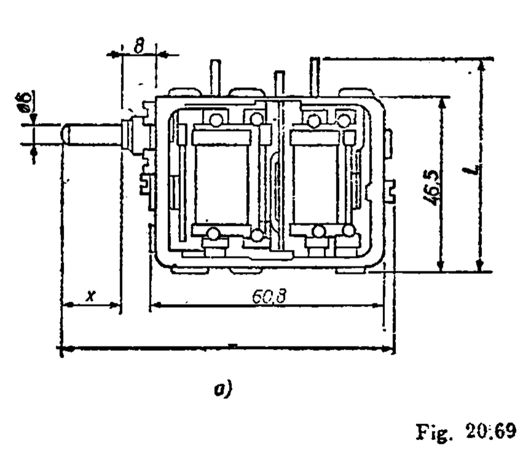
Dimensions in mm (fig. 20.69 a): overall length L, width l (frame with its terminals) and shaft length x from the table; frame 60.8 × 46.5, shaft Ø 6. „ΔC AM” and „ΔC FM” in the Variants table are the largest values of the curves (curve d: ΔCcor 388.5 pF, ΔCosc 323.8 pF); they are left out where the printed curve is of the other kind (P 22099 G, P 21710 D) [1].
Gallery
 No image available
Documents
No documents available yet.
References
- [1]N. Drăgulănescu – „Agenda radioelectronistului”, 2nd edition, Editura Tehnică, 1989, section 20.4.5.8 „Condensatoare variabile cu aer”, pp. 305–308
- [2]N. Drăgulănescu – „Agenda radioelectronistului”, 1st edition, Editura Tehnică, 1983, section 3.5.4.5.8 „Condensatoare variabile cu aer”, pp. 274–277
- [3]N. Drăgulănescu – „Agenda radioelectronistului”, 2nd edition, Editura Tehnică, 1989, sections 20.4 „Condensatoare produse în R.S.R.” (p. 248) and 20.4.5.1 „Codificare – marcare (în clar)” (p. 301)
- [4]N. Drăgulănescu – „Agenda radioelectronistului”, 1st edition, Editura Tehnică, 1983, sections 3.5.4 „Condensatoare produse în R.S.R.” (p. 218) and 3.5.4.5.1 „Codificare – marcare (în clar)” (p. 270)
- [5]D. F. Lăzăroiu, N. Millea et al. – „Electronica românească. O istorie trăită”, vol. I, AGIR, section II.6 „Componente, subansamble și ansamble conexe”, II.6.3.2.2 „Condensatoare variabile”, p. 268